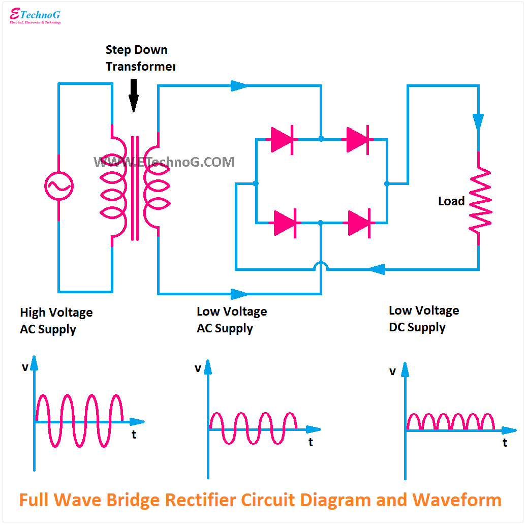
Full Wave Bridge Rectifier Circuit Diagram Bridge Rectifier
Rectifier wave bridge full circuit diagram diode voltage operation fig its shown below inverse peak disadvantages advantages value when Half wave full wave and bridge rectifier diagram Full wave bridge rectifier schematic
Full Bridge Rectifier Working
Full wave bridge rectifier circuit diagram Full-wave bridge rectifier circuit Full bridge circuit diagram
Full wave bridge rectifier
Full wave bridge rectifier pcb designs imagesFull bridge rectifier working Full wave bridge rectifier lab manual 15+ pages solution [3.4mbIn-depth guide to full wave rectifier.
Rectifier wave bridge full operation half working animation input current cycle positive forward during gif diodes reverse biased d3 d1Full wave rectifier circuit diagram class 12 Bridge rectifier wiring diagramExplain full wave bridge rectifier with diagram pcb designs.
![Full Wave Bridge Rectifier - Circuit Diagram, Working & Waveforms](https://i2.wp.com/electricalworkbook.com/wp-content/uploads/2021/07/Full-Wave-Bridge-Rectifier.png)
Full wave bridge rectifier
Bridge full wave rectifier circuit diagramIn-depth guide to full wave rectifier Full wave bridge rectifier download scientific diagramFull wave bridge rectifier schematic.
Full wave bridge rectifier operationBridge rectifier wiring diagram The full-wave bridge rectifier.
![Full Wave Bridge Rectifier - its Operation, Advantages & Disadvantages](https://i2.wp.com/circuitglobe.com/wp-content/uploads/2015/12/FULL-WAVE-BRIDGE-RECTIFIER-FIG-5-compressor.jpg)
![The Full-Wave Bridge Rectifier - Last Minute Engineers](https://i2.wp.com/lastminuteengineers.b-cdn.net/wp-content/uploads/2020/02/Fullwave-Bridge-Rectifier.png)
![Full Wave Bridge Rectifier Schematic | My XXX Hot Girl](https://i2.wp.com/dwma4bz18k1bd.cloudfront.net/tutorials/Bridge-Full-Wave-Rectifier-Typical-Application-Circuit.png)
![Explain Full Wave Bridge Rectifier With Diagram Pcb Designs - Riset](https://i2.wp.com/www.electroduino.com/wp-content/uploads/2021/04/Full-Wave-Bridge-Rectifier-–-Circuit-Diagram-and-Working-Principle.jpg)
![Bridge Full Wave Rectifier Circuit Diagram](https://1.bp.blogspot.com/-ph3wPcxTMhg/YO60L9F14dI/AAAAAAAABM0/svLo3j9BnrEtn4_4Ldv94ZgxqVJXvAE7ACLcBGAsYHQ/s1035/Center%2BTap%2BFull%2BWave%2BRectifier%2BCircuit%2BDiagram.png)
![Full Wave Bridge Rectifier Circuit Diagram](https://i2.wp.com/www.circuits-diy.com/wp-content/uploads/2021/06/full-wave-bridge-rectifier-circuit-diagram-schematic.png)
![Full Bridge Rectifier Working](https://3.bp.blogspot.com/-StSuJoNc97k/UL8qokwTRKI/AAAAAAAAI3I/yiLI4VrqTsI/s1600/Figure+6.3+3-PHASE+FULL-WAVE+RECTIFIER.jpg)
![Full Wave Bridge Rectifier Download Scientific Diagram - Riset](https://i.ytimg.com/vi/WSHVg9Cdg1s/maxresdefault.jpg)
![half wave full wave and bridge rectifier diagram - Wiring Diagram and](https://i2.wp.com/circuitglobe.com/wp-content/uploads/2015/12/FULL-WAVE-BRIDGE-RECTIFIER-FIG-1-compressor.jpg)
![Full Bridge Circuit Diagram](https://1.bp.blogspot.com/-uzWX38U8Hjs/YO60pnoF8UI/AAAAAAAABM8/otQyNJpK8PIUk9vmeOwTroo0cMf9xL06ACLcBGAsYHQ/s16000/Full+Wave+Bridge+Rectifier+Circuit+Diagram.png)