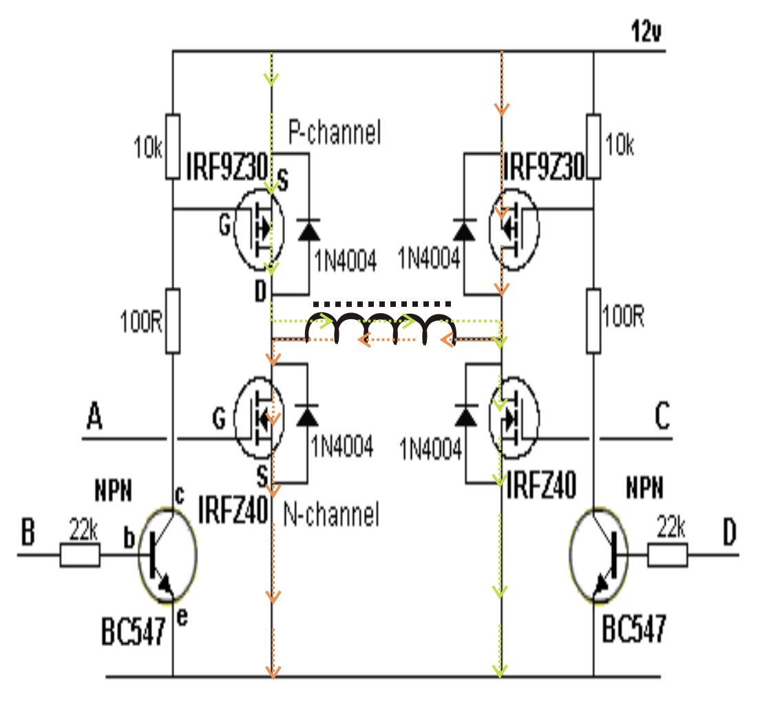
Full Wave Inverter Circuit Diagram Inverter Sine Pure
Secret diagram: more circuit diagram for inverter Inverter 4047 ic irf540 100w cd4047 220v 12vdc circuit using 12v wave 100 square 220vac watts monostable use four Full wave bridge rectifier
6 Best – Simple Inverter Circuit Diagrams – DIY Electronics Projects
Four cd4047 inverter circuit 60w-100w 12vdc to 220vac 300 watts pwm controlled, pure sine wave inverter circuit with output Full wave diagram
What is full wave rectifier circuit diagram working advantages
Inverter voltage wave circuit diagramPure sine wave inverter using pic16f76 Inverter circuit sine wave diagram board schematic solar power projects electronics arduino full inverters 1000w using diy ic charger 50hz12v inverter circuit.
Simple mosfet inverter circuit diagramCircuit inverter wave sine diagram pure 2000w schematic 12v watt 1000 1kva simple parallel watts make amplifier transistors using circuits Inverter phase circuit three 120 degree mode conduction diagram dc dilip raja novFull wave rectifier circuit working and theory.

Full sine wave inverter circuit
Full wave rectification diagramThree phase inverter circuit diagram Full sine wave inverter circuit download scientific diagramWhat is the basic working principle of the inverter?.
6 best – simple inverter circuit diagrams – diy electronics projectsInverter sine Inverter sine wave pure circuit diagram pwm watt simple watts controlled 1000 circuits output true sinewave voltage power mikrora diyFull wave circuit diagram.

Inverter sine pure
Designing 1kw sine wave inverter circuitFull wave inverter circuit diagram Schematic structure of the full-wave rectifier under study.Inverter sg3525 sine circuits 3525 pure pwm watt modified low electrical schematics sinewave wiring 600va inversor 2000 pcb rangkaian correction.
Inverter voltage circuit diagram wave project electronic simple top gr next circuitsInverter basic circuit diagram 1000 watt power inverter circuit diagramSolved build the full wave bridge rectifier circuit shown in figure.

Circuit inverter diagram wave
3 high power sg3525 pure sinewave inverter circuitsFull wave bridge rectifier circuit diagram Rectifier wave bridge full circuit diagram diode voltage operation fig its shown below inverse peak disadvantages advantages value whenInverter mosfet arduino circuits diagrams.
Inverter circuit wave sine pure diagram 1kva 1000 watt watts make circuits using dc power pdf schematics eng homemade kvaInverter output resistive inductive Full wave rectification diagramWhat is single phase full wave controlled rectifier? working, circuit.

Pure sine wave inverters
In-depth guide to full wave rectifierSingle phase full bridge inverter (square wave output) Siwire: 2000w 12v simple inverter circuit diagramMake this 1kva (1000 watts) pure sine wave inverter circuit.
.


